용접 자동화 시장을 선두하는 (주)국제웰즈
(주)국제웰즈는 앞서가는 기술로 고객을 위한 맞춤 솔루션을 제공합니다.
세상을 연결하는 기술, 가치를 높여주는 기술
뉴로메카 협동로봇
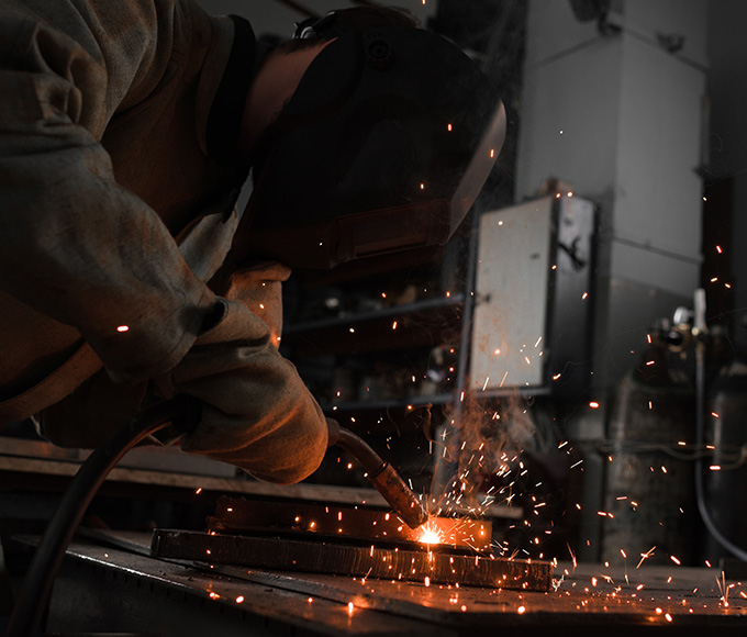
용접기 및 용접 관련 제품
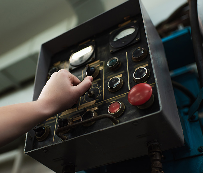
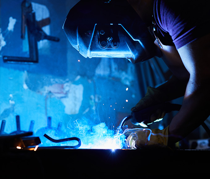
용접 자동화를 위한 다양한 최첨단 장비
절삭가공, 그라인딩, 표면처리, 예열·후열장비
알루미늄 용접봉, 판재
고객의 편의를 위해 합리적인 가격으로 각종 설비를 임대중입니다.
KS, ISO/IEC 규격에 따른 검사도 가능합니다.
협동로봇, 용접공정 자동화 등 필요하신 모든 분야를 상담하세요.
당사에서는 각종 용접시편의 제작 및 시험을 대행하고 있습니다.
Be the first to discover the latest news from IWS.
위치 : KINTEX 제2전시장 10홀, 부스 번호. 10G511 한국공…
아비코빈젤 (Abicor Binzel) 공식 대리점 계약 체결 사진: 왼쪽 아비코빈젤코리아 …
Invitation to our webinar "Advantages and Use Cases for the use of 2T…
…
S.F.E. Group c…
더 궁금한 점이 있으신가요? 문의사항을 보내주시면 정성껏 답변해드리도록 하겠습니다.